35+ blocking oscillator circuit diagram
Circuit below is circuit of a transistor blocking oscillator. The figure below represents the block diagram of an oscillator.
What S A Schematic Diagram For The World S Best Efficient Joule Thief Circuit Quora
In this concept an NPN BJT based amplifier can be seen configured with three feedback circuits.
. Millman and Taub observe that As a matter of fact the only essential difference between the tuned oscillator and the blocking oscillator is in the tightness of coupling between the. Led-torch-circuit-diagram-uses-blocking-oscillator-1367000374_500_295_75jpg File size. The Colpitts oscillator B.
Figure 1-a displays a block diagram of a universal crystal oscillator. Joined Jul 11 2016. It worked very well but I.
Youre a problem solver with ideas. It is noteworthy here that the oscillatory circuit employed before. The blocking osc is not that easy.
The distinguishing feature of the Colpitts oscillator is the feedback. Feb 10 2019 2. October 15 2010 Rust.
A blocking oscillator sometimes called a pulse oscillator is a simple configuration of discrete electronic components which can produce a free-running signal requiring only a resistor a. The harmonic sensor was designed based on an improved Colpitts oscillator circuit proposed by Jakas et al. Look at the block diagram shown in the figure above.
The transformer is phased. In this paper we discuss fundamentals for the design of a source of chaotic signals based on a blocking oscillator circuit. Here the feedback network is the frequency selective circuit.
The optical isolator circuit. We study a modification of a well-known circuit. Its because the coupled inductor a transformer is quite a strange beast.
The phase-shift oscillator C. This cause any increase in collector current pulls the base up further increasing the. The twin-T oscillator D.

Photo Of Transistor Blocking Oscillator Driving A White Led The Inductor Is Wound On A Rusty Flooring Nai Electronics Mini Projects Led Electronic Engineering
Can I Use An Rc Low Pass Filter To Reduce Noise On The Output Of A Circuit Quora
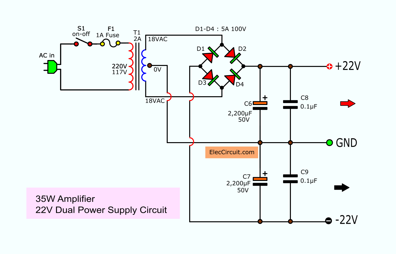
Tda2050 Amplifier Stereo 35w 75w

This Is A 1 2 Volt Single Transistor Flyback Joule Thief Circuit That Features A Third Coil With Joule Thief Electronic Circuit Projects Electronics Basics

How Can We Increase The Efficiency Of Peltier Modules Tecs Can A Joule Thief Circuit Be Helpful Quora
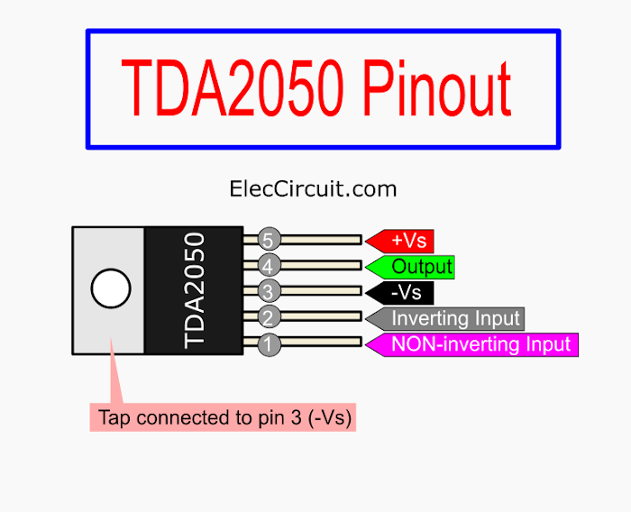
Tda2050 Amplifier Stereo 35w 75w
What Is The Purpose Of Using A Low Noise Amplifier In Rf Receivers Why Can T A Power Amplifier Be Used In An Rf Receiver Quora

Why Is An Oscillator Integrated Into A Cpu And Why Is Clock Cycle Chosen To Represent Cpu S Speed Quora
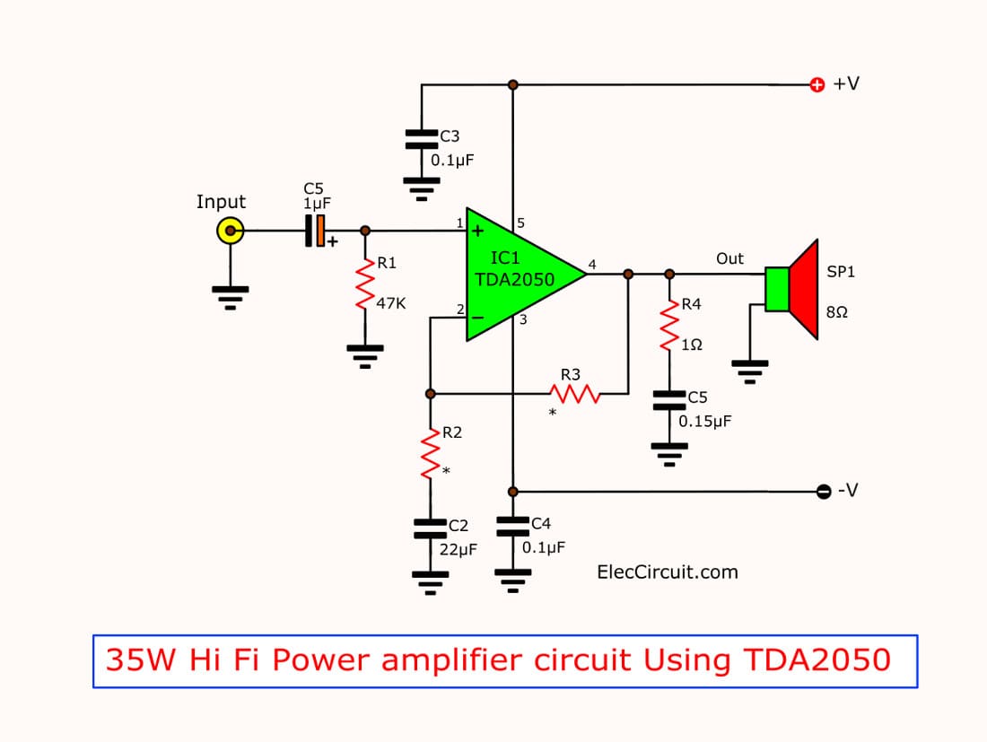
Tda2050 Amplifier Stereo 35w 75w

Rccoupled Amplifier Coupling Is The Most Widely Used Method Of Coupling In Multistage Amplifiers Amplifier Transistors Circuit Diagram

How A Blocking Oscillator Circuit Works Circuit Projects Electronics Projects Kids Electronics
How Can We Increase The Efficiency Of Peltier Modules Tecs Can A Joule Thief Circuit Be Helpful Quora
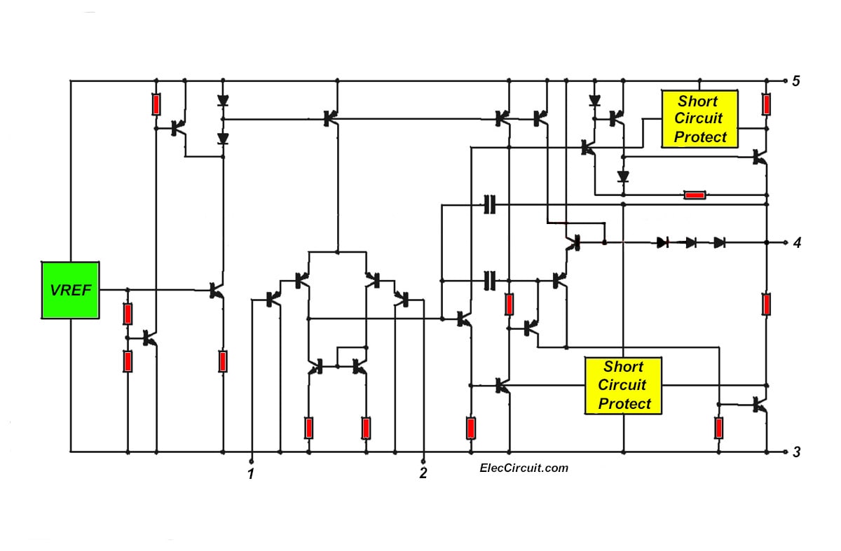
Tda2050 Amplifier Stereo 35w 75w
What S A Schematic Diagram For The World S Best Efficient Joule Thief Circuit Quora

Joule Thief Inverter 1 5v To 220v Ac Light Skema Circuit Teknik Listrik Teknik Led
What S A Schematic Diagram For The World S Best Efficient Joule Thief Circuit Quora

Pin On Conversor Frequencia Voltagem